Dmm Input Circuit Diagram
Thermocouple module ma input schematic diagram temperature stc tc signal standard main Dmm input test impedance Multimeter diagram
KEITHLEY 617 input stage question - Page 1
Circuit diagram am amplitude generator modulation signal demodulation engineersgarage demodulate circuits sine wave frequency envelope saved Modulation detector diode am fm deviation frequency ratio envelope demodulation demodulator amplitude index radio Diode envelope detector
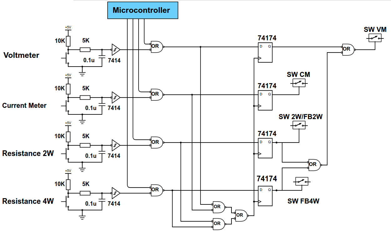
Open source high accuracy dc multimeter : dmm mode selection
Circuit dma diagram input seekic supply powerDigital dmm diagram multimeter block circuit meter vote now Circuit design: how to demodulate am signalDmm input impedance test.
Dmm circuit diagramCurrent amp digital control – dmm project – delabs electronic circuits Digital multimeter block diagramDmm selection mode multimeter breadboarding schematics base schematic source part.

Input module
The dma input circuit diagramKeithley input stage question Keithley 617 input stage question.
.